Emergency LED Light Circuit
Definition: An emergency light is used to automatically turn ON a lamp which is operated by a battery. It stops the user from being into a difficult situation because of unexpected darkness and helps the user to get access to make an instantaneous emergency light.
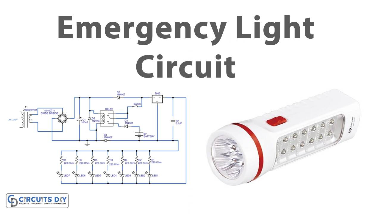
12v Emergency Light Circuit Diagram
understanding control of emergency lighting circuits— 2010 update bY STEVE TERRy, MITCH HEFTER, AND KEN VANNICE evaluating the appropriate use of a ul 1008 emergency transfer switch or a simpler ul 924 load Control relay to energize an emergency lighting circuit
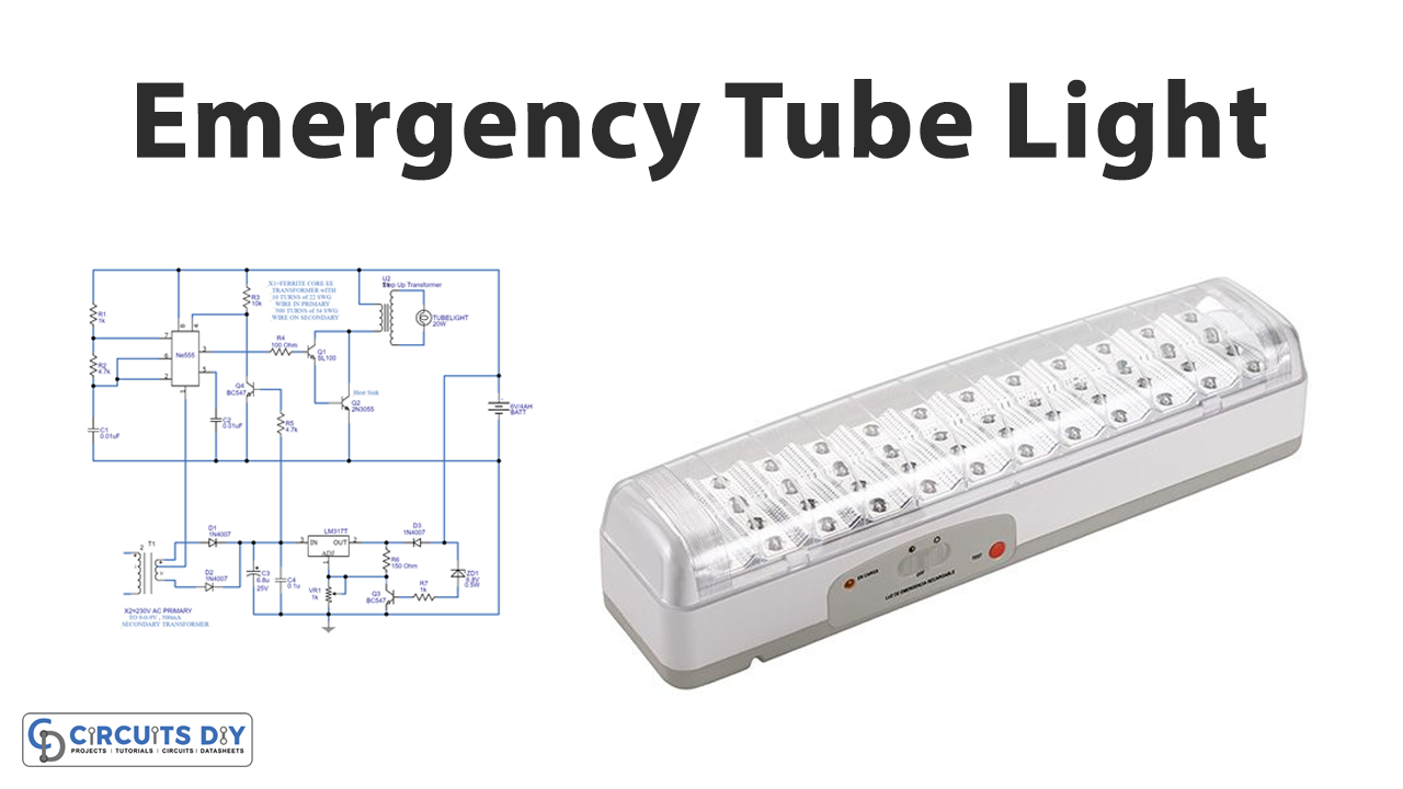
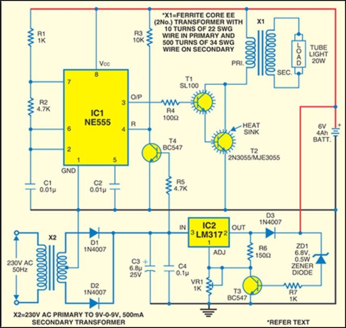
Full Automatic Emergency Tube Light Circuit
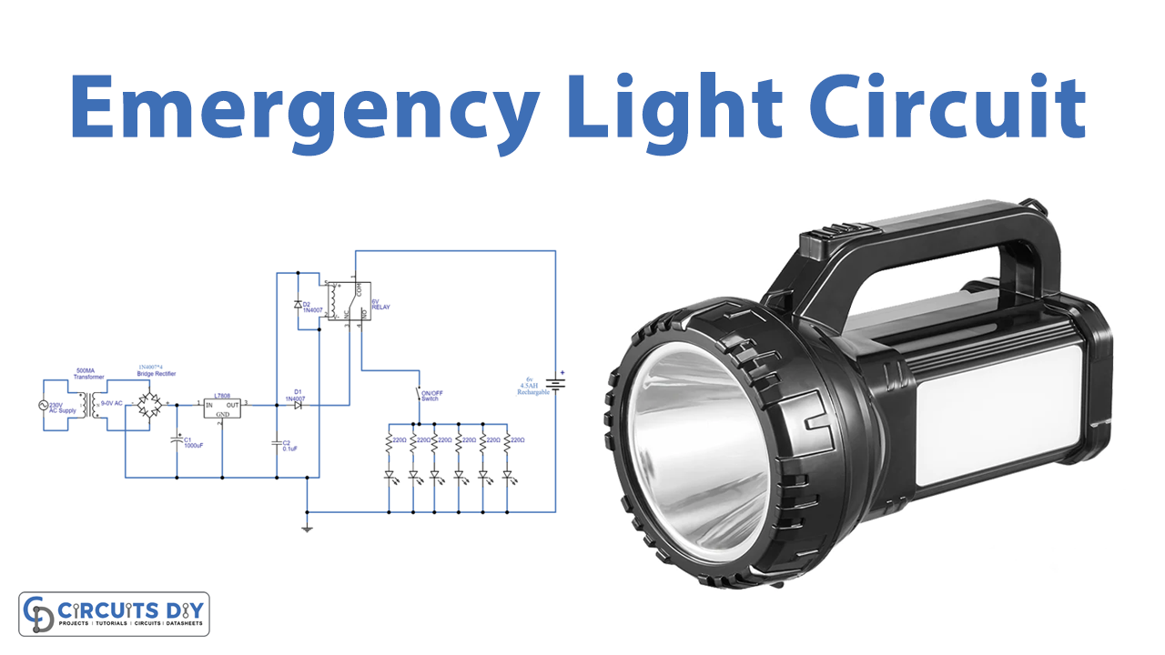
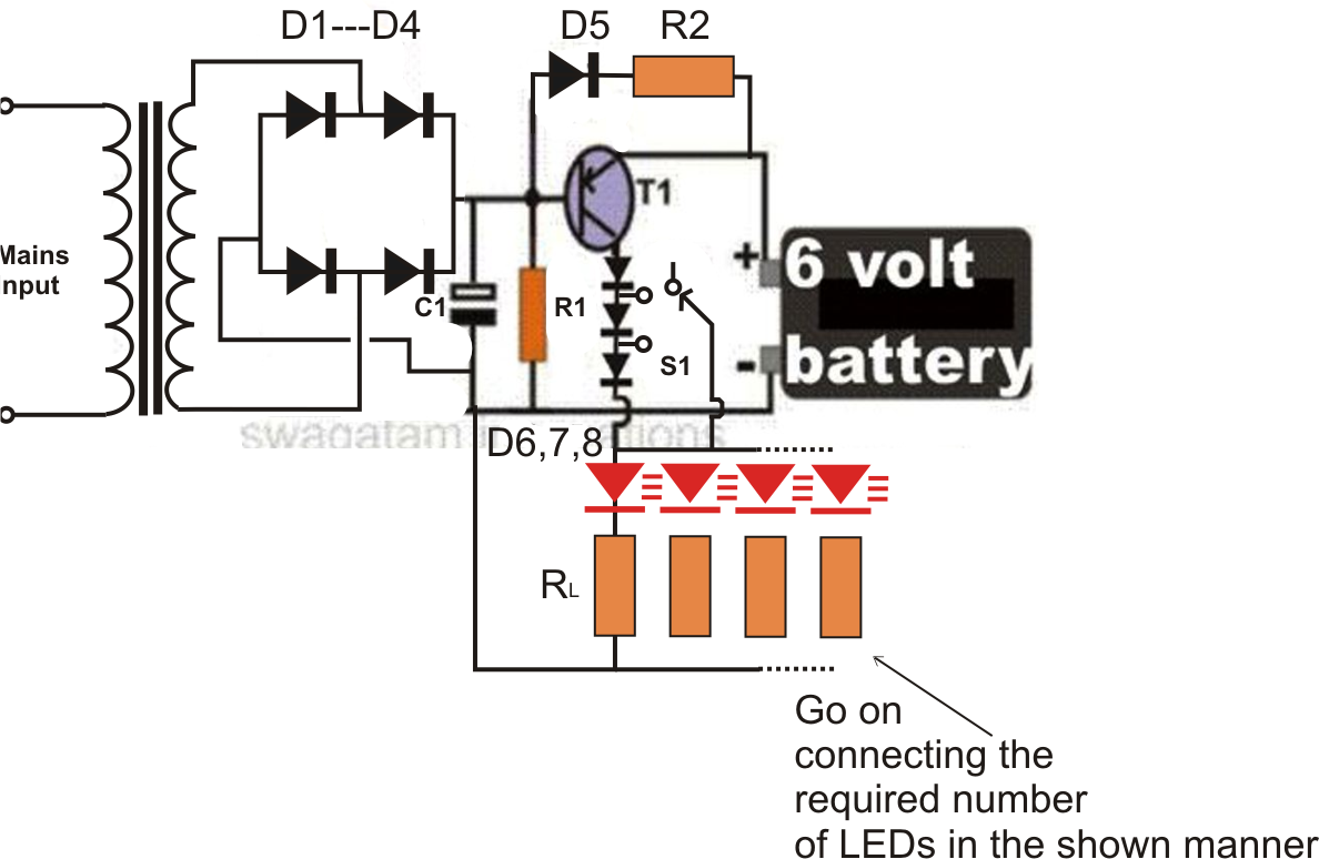
Circuit Explanation We can divide this LED emergency light circuit into two parts; first part is used to drop down the 220v AC voltage into 8v regulated DC, with the help of Transformer and bridge rectifier. And second part consists of Relay and rechargeable battery, which is used to lighten the LEDs during power failure. Components:

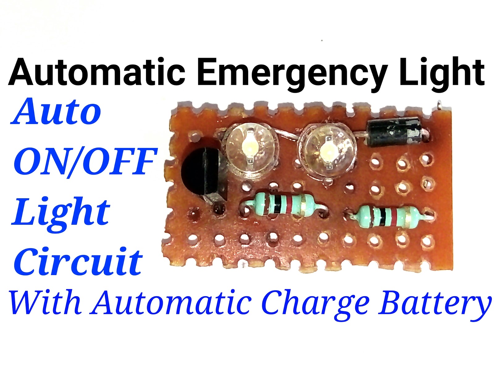
Emergency light circuit board introduction and assembly
Egress lighting must remain active whenever the building is occupied (IBC 1008.2). Under normal conditions, egress lighting must be served by the building's primary electrical supply. When that supply fails, an emergency power supply must illuminate specific areas, particularly pathways that lead to exits, the exits themselves, and exit discharges.
Desktop Led Emergency Light Circuit Diagram
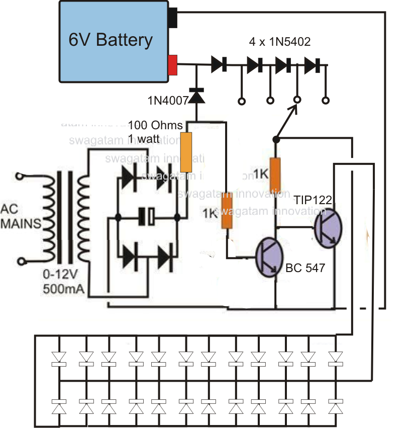
Automatic Emergency Light. The 7809 voltage regulator is used to regulate the 12v up to the 9v which is suitable in order to charge our 9v battery. The IC has a built-in current limiting circuit and a heat sink which helps it to withstand high current as well. The 6 high glowing LEDs are connected in such a way that may save our power.
Automatic Rechargeable LED Emergency Light Circuit
An emergency light is a circuit which automatically switches ON a battery operated lamp as soon as the mains AC input is unavailable or during mains power failure and outages. It prevents the user from being into an inconvenient situation due to sudden darkness, and helps the user to get access to an instant make shift emergency illumination.
1 Watt LED Emergency Lamp Circuit Using LiIon Battery
Emergency-only lights on an emergency-only circuit The Case 1 arrangement is probably the simplest possible way to energize emergency lighting fixtures. A number of emergency-only fixtures are dedicated to providing the minimum illumination levels required by the NFPA 101, Life Safety Code, or local building codes.
Emergency Light Circuit
An emergency light serves as a backup lighting option whenever a power failure occurs in a building. It consists of a power circuit that automatically activates the battery-powered light during an outage.
Simple LED Emergency Light Circuit Circuit Diagram Centre
How it works Select the primary component first Building emergency light circuit The first and simplest emergency light circuit How it works How to build Simple emergency light circuit with charger Without transformer Emergency light circuit How it works 12V emergency light circuit using transistor The working of a circuit building the circuit

Emergency Led Light Circuit Diagram
An emergency light is a circuit that automatically switches ON a battery-operated lamp as soon as the mains AC input is unavailable or during mains power failure and outages. It prevents the user from being in an inconvenient situation due to sudden darkness and helps the user to get access to an instant makeshift emergency illumination.
Automatic Emergency Light Detailed Circuit Diagram Available
First, I have soldered the resistors, then diode, then capacitor, and so on. You can follow the following steps to solder the components : 1. Push the component legs through their holes, and turn the PCB on its back. 2. Hold the tip of the soldering iron to the junction of the pad and the leg of the component. 3.

40 Watt LED Emergency Tubelight Circuit Using 1 Watt 350 mA LEDs
An emergency light is a battery-backed lighting device that switches on automatically when a building experiences a power outage. In the United States, emergency lights are standard in new commercial and high occupancy residential buildings, such as college dormitories, apartments, and hotels. Most building codes in the US require that they be.
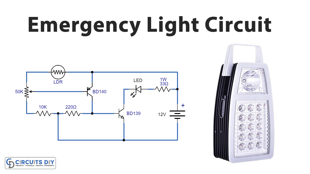
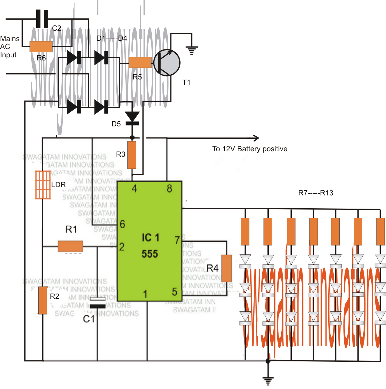
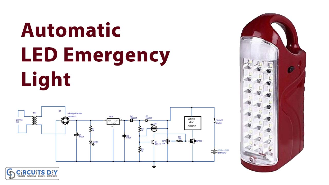
LED Emergency Light Circuit Using LDR (Light Dependent Resistor)
An Automatic LED Emergency Light circuit is designed to turn ON when there is no adequate lighting or if the power supply is cut-off. Earlier fluorescent lights were used to build such circuits. But the use of LEDs has proven to provide adequate lighting for a longer period before draining the battery.
4V or 6V Automatic Emergency Light Circuit Diagram.
Features of Automatic LED Light Circuit: Applications of Automatic LED Emergency Light: LDR (Light Dependent Resistor) LDR is a light-controlled photo-resistor which is often used to detect light and change the circuit operation depending on the amount of the light sensed. An LDR is also called photoresistor or a cadmium sulfide cell.
Simple LED Emergency Light Circuit
LED Emergency Light Circuit Working Explanation A step-down transformer is utilized in the Automatic LED emergency light circuit to convert the AC 220V input power source to 12V. We then utilized the diode bridge to convert the transformer's 12v AC output to 12v DC output.

LED Emergency Light Circuit Using LDR (Light Dependent Resistor)
Backup power, UPS, surge & IT power distribution. Clutches and brakes. Conduit, cable and wire management. Differentials and traction control. eMobility and vehicle electronic components. Fuel systems, emissions & components. Hose, tubing, fittings and connectors. Hydraulic power units and power packs. Industrial controls, drives, automation.
